Showing posts with label Phaserion. Show all posts

Sunday, September 22, 2013

An update on Phaserion & Variator: After three years...

Assalamu'alaikum everyone,

It has been a slow year for all of us are busier than ever. However, we're still burning with project ideas. On my side, I have just setup my small working area and I have been using the Phaserion & Variator for three years. (It has been that long? Whoa!).

This time, I'm going to provide some updates on Phaserion, which I think is a very handy equipment I have built all these years. It is an adjustable power supply with a range of 1.5-22V, and I have been using it for just about everything for my electronics projects. 

This is a video of the addition I made for the Phaserion:

Variator with a shiny new display

The feature addition on the Phaserion is pretty important- I added a 7-segment display to indicate the voltage, which is helpful if you have various projects with different supply requirements. The PIC used was the ever-so-simple PIC16F876 (Which I first bought after looking into Nigel's tutorials) and I think it is high time it is permanently embedded into a proper application gizmo for all that I've learnt from Microchip's PICs. We'll have a small tutorial on the 7-segment later, in which the programming was done using MikroC. (I don't think I could have progressed well in my programming if I'm stuck to Assembly language. No hard feelings there Uncle Nigel.). Here's the additional circuit:


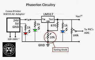
A bit of a stumbling block here- How do I detect 22V when PIC is capable only up to around 5V? The answer is simple: A trimpot. Install a trimmer between the output power, and let it swing to it's maximum output. After doing so, slowly tune your pot to give a 5V output. Therefore the output is now 22V Ξ 5V. Swing your voltage down. It will rescale to a lower voltage! 

Some of the pictures may speak a squillion words:


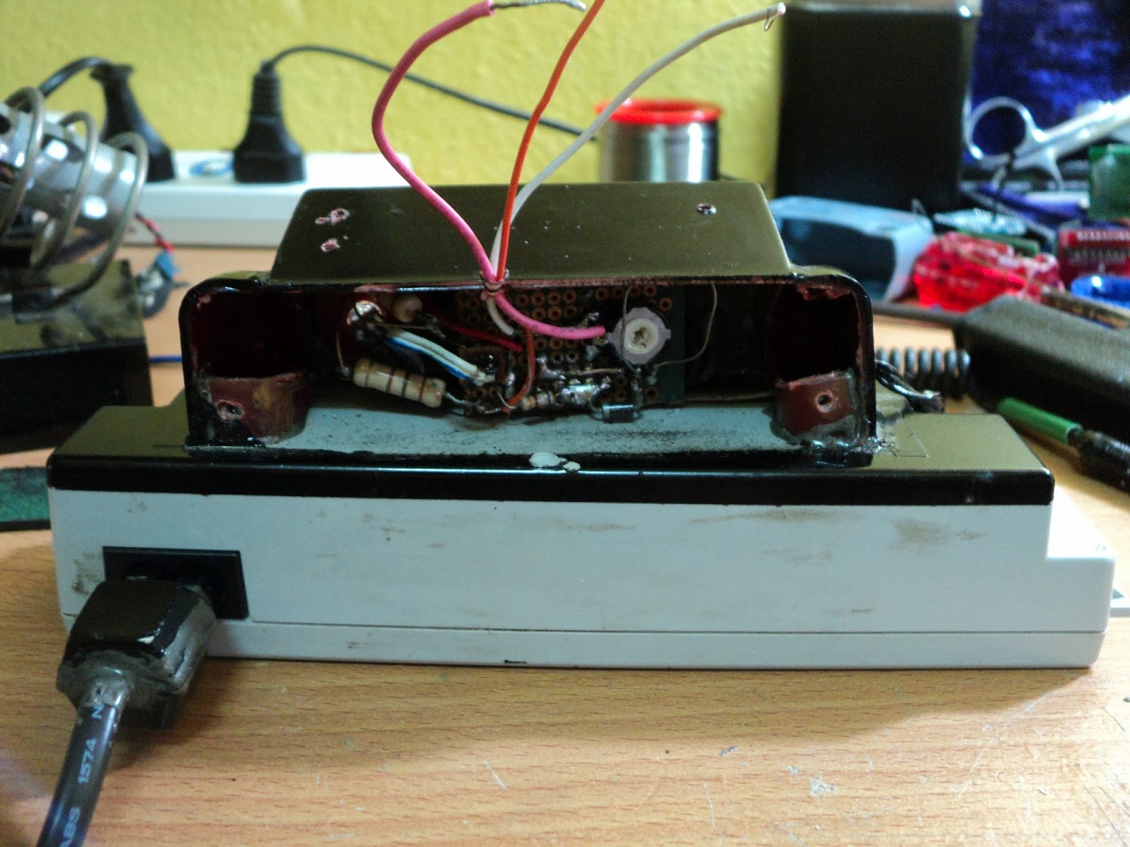
You can see that black-and-white trimmer/trimpot (bought when I was shopping with Beautifulmind seven years ago, you know!) for scaling down 22V maximum swing to a 5V  maximum swing... that'll be for the PIC.


Phaserion adapted for my Starke drill batteries' charging

...and it can be used for my breadboard supply

...Yup. I used my old Chinese multimeter terminals for an in-situ power supply (good for testing nook-in-the-crannies)

Adapted for crocodile clips as well (Just for show dudes)

And since we have so many cables, a good way to organize them would be to use small cardboard cylinders to store 'em cables. Trust me, a good working space is a TIDY one.

So that's all for this article. The circuit addition is pretty simple but we'll cover that later in more detail when the 7-segment tutorial is done.

Keep on Vortexifying everyone! 
Regards,
Vizier87.

Thursday, March 24, 2011

Construct your own DC Power Supply Mark II : Phaserion reporting.


All Glory to the Almighty Allah who governs every detail of our life. No one can do anything except with the will of Allah SWT.

As told before, this is the sequel of the article about Wall Warts before this. So.. this article focuses on more structural insight, which is very simple but saves a lot of money. Before this, I used an adapter which has tuning knobs to it. However, the voltages are fixed with a fixed increment of several values. So... Some kindergarten electronics to kick in!

Initiation

This time, I want more freedom in choosing a voltage, and I have a very good quality adapter for this purpose. The one I obtained looks like this:


A Canon K30155 AC Adapter for printers, where I keep busted printers and managed to scavenge this. The other components below are some of the parts needed for the construction of the prototype; a perfboard, a plastic tuning knob from an ancient radio, a potentiometer and an LM317 Variable Voltage Regulator.

From the adapter, there are two outputs, a 5V/0.2A rail and a 24V/0.55A rail with respect to a common ground. So, I'd like to channel the 25V out to be fed into a regulator, which in our case is an LM317. The LM317 has a maximum current output of 1.5A so the adapter is tolerable for output variation.

The circuit to vary the voltage is very simple, as shown in the datasheet:


Construction

So from the structure of the adapter, it's quite obvious how would it serve its purpose as a Power Supply, where it acts as a platform. Now.. Some imagination would be useful:


You may need to open the figure above in a new tab if you'd like a closer look. *winks*
So.. from the figure:

1. Plastic panels from an old clock.... looks pretty suited for the job.

2. Estimates of the dimensions so that the circuit and everything else fits in properly. The springy cable is from an old phone charger, I thought it's very good for messy jobs where you might tug your circuits accidentally, so the springy part sort of absorbs some motion. Just an idea guys... no need to follow everything.

3. Holding the structure using rubber bands so that rigidity is achieved for the epoxy glue to dry out properly. Note that the epoxy glue is applied on the inner side so that the smear of the glue is not exposed. For aesthetic purposes. (Rubber bands? Oh noooo....Nah, it's okay, they're proper for the job)

4. The curved plastic sides added, also from the clock panels, glued accordingly.

5. Added the small plastic pieces to act as a platform for the screw threads for the panel to close the opening.

6. The front view, see the parts where the epoxy glue fills in. Also, the previous Variator Wall Wart is shown there for size comparison. Note that they have the same output socket to be plugged into the conditioning circuit, so it's easy for us to alternate between the two supplies according to our preference without changing the interfacing power sockets.

7. Added indicator LEDs for three categories: A green LED to indicate the input power to the regulator, a red LED to indicate the 5V rail, and blue for the 24V rail. Note that for the LED which is powered from the 24V rail, we'll need a Resistor with a higher tolerance. Also, note that the technique used to protect the wiring is similar as shown in the Variator article, where I encased the wiring using a pen casing, glued to the male socket.

8. Plastic panel cut to size as closure, which can be reopened for inspection if necessary.

9. Just a dash of aesthetics... sprayed black paint at the upper part of the structure.

10. Phaserion Power Supply completed. Below, the circuitry of the Phaserion is provided.


Foreclosure of a Design.

Now.. at last, just for fun, I also would like to construct the plug to supply from the mains, but just so you guys know, there are ratings of the wiring which may be ahead of you guys, so do this only under supervision from someone who has electrical knowledge. I take NO responsibility if you get yourself injured through electric shock. This part is not necessary if you already have your own standard main power plugs.


So... knowing the risks mentioned, we proceed:

1. A plug from a CRT circuitry which fits the dual terminals of the adapter, an ex-soldering iron cable (you know... they get damaged easily, especially the cheap ones.. so just so that you know, I prefer Ceramic Heater Soldering Irons. ) .... and to cover the whole thing, I used scavenged keyboard buttons to encase the exposed part of the wiring.

2. Soldered the terminals.

3. Some extra insulation using electrical tape, and fitted into the keyboard buttons, which now serve as a casing.

4. Press 'em using the cute G-clamp and glue 'em.

5. After drying, fit and a dash of black spray paint, you can try it.. looks like any normal plug, hopefully. *winks*.

6. The LEDs light up, ready to be used.

Conclusion

So... there you are. The structure is simple, rigid, and insyaAllah will last for a long time. The Recycletronics theme is still utilized at its best in this project, where I probably used up around only a few ringgit. Useful for research projects and prototyping as well, and you don't have to fish out fifty bucks for branded DC supplies... just fish out your junk and use the rest of the money for charity.

I named this prototype Phaserion because the variation of the voltage can be changed accordingly, so as to a phase shift. So there you go: Phaserion and Variator, working in tandem.

May Allah be pleased with us when we reduce our expenses for ourselves and more for other people who may need more.

All the best to the ones out there.

Sunday, March 20, 2011

Construct your own DC Power Supply Wall Wart! Variator Reporting.

Alhamdulillah. All Praises to Allah SWT who created and governed everything in this world.

So guys.. we'll be doing something very important for hobbyists here. All electronic circuits require a steady power supply, and you'll get fed up using batteries for testing purposes, which run out of juice for only an hour's worth of running time.. That excludes the electrolytes which leak out after some time.. (NOOOO!!!).....

So.. normally people would opt to: Buy a costly DC wall wart, with fancy controls and an indicator (which is sometimes deceiving) and risk thinning your wallets......

.....or construct their own by buying cheap DC supplies and hacking it to suit their applications. In my experience, after some time the cheap DC supply will be overheated and you'll be left with a fuselage of burnt plastic and a dead transformer.

....or you can opt to take a leaf out of the book of Vortex Electrica and use your own adapters in your house. There are tons of adapters for various applications; Laptop chargers, printer adapters, cellphone chargers (especially old ones), and so on. What's the difference between the ones you buy? Normally adapters for branded stuff have more quality and more protection circuitry. So... This is my collection:


A lot huh? Some of 'em are damaged, and some are okay. Each can be tested easily using an LED and a 100 ohm resistor.

So... the obvious steps for anyone with basics is to cut the wires loose and connect crocodile clippers to them, right?

WRONG! From experience, the weak points are always attributed to the connection between the wire and clip, because the CLIPS SUFFERS THE MOST MECHANICAL STRESS HERE, SO THEY BREAK APART EASILY AFTER SOME TIME. So if you don't want to have to repeatedly re-solder the clips to the wires, the best thing to do is to make separate connections, which can be plugged when in use. In short, see below:


So.. the figure should give an idea. Also, this means that the power from the DC adapter can be plugged into other circuits i.e not only the crocodile clips but also to a breadboard, or any other devices which have the corresponding socket to fit.

Now, another series of ideas comes into play: I want to have.....

a. indicators to know that it is ON, and
b. I want to be able to switch ON/OFF the power at hand, not at the mains where things might get messy, and
c. I want it to be STABLE, not fluctuating power, and
d. I want it to be VARIABLE, not fixed.

So the rest is easy... Add a green LED to indicate ON, a mono-state switch, a filter monolithic capacitor across the terminals, and a variable voltage regulator, like an LM317 or other equivalent components. In short, everything'll look like this:


So as we go along I'll explain the tips and tricks I employed, which may be of use, since we're all about IDEAS at the first place. So here goes:

First Prototype:
VARIATORTM
Wall Wart (I named it for reference... Heh heh..)


So the figure shows some simple stuff:

1. Solder the male socket wiring to the Adapter wiring. In this picture, notice that the GREY insulation is there, standing by to sheath the exposed soldered part of the wiring. This means BEFORE soldering, fit in the insulation first. You can get that type of insulation from various types of wiring which has thicker wires.

2. The exposed part of the wiring is now covered properly by sliding the grey insulation over it. Take note that you have to make sure the inner part of the wiring is also insulated so that no short-circuit takes place. Note that the adapter has a tuning knob there, with fixed values from 3.0,4.5,6.0,7.5 until 21 Volts.

3. Now, add a plastic cover over all the stress points, and glue it accordingly. This makes a nice, difficult-to-break-apart socket. This means if there are any mechanical stress suffered by the socket, the wiring will out of the way, and the plastic cover will take the load. The figure below explains better:


See that the one on the left is one without the casing, so the break points are easily formed at the soldered points, rather than the one on the left, where the load is shifted to the plastic casing, reinforced with epoxy glue.

Next, a conditioning circuit is shown here:


The conditioning circuit is also a separate entity, as declared in the plan before, which fits in a green indicator LED, an ON/OFF switch, a freewheeling diode (to counter backward EMF spikes), a filter capacitor to stabilize supply, and a female USB port.

Now, why did I use a USB socket? Because I have a lot of 'em, and they don't leave room for reverse connection, which could be disastrous. The male USB connector is wired to the crocodile clips, which we'll explain in the following. USB ports have four terminals, so I combined two terminals together to get two crocodile clip terminals.

So now.... The crocodile clips. The main problem with most clips is also due to the mechanical stress it faces. So here's my design:


So the epoxy glue is very important to secure the connections. Also, the plastic casing protects the wiring and shifts the mechanical load of the wiring to itself. The USB socket is a bonus; it's strong and has only a single orientation when you plug it.


The figure above shows the transition according to the design mentioned above.
First, fitting the wires inside the plastic casing. I must warn you, it is pretty tricky to fit in the wires in such a cramped space.
Second, the clips' wiring and gluing is done.
Third, just to show when everything's in place.

So, the conclusion is that while it takes a bit more time to do this, you'll save more time than attending to the wires again and again when they break off due to the wear and tear effect.

So that's it! You have a sturdy Wall Wart for yourself and you don't need to spend much in constructing one. A variant of this (more hardcore DIY-ing) will be provided in future articles, InsyaAllah. For such a simple project, a lot of drilling down is done to provide IDEAS. So.. hopefully some of them will be of use.

All the best to ones out there struggling with their lives... May we live to please Allah more.
Related Posts Plugin for WordPress, Blogger...