
---------------This article has a moderate difficulty level in construction.--------------
Remember that the documentation regarding this article is pretty scarce, since most of the sensors out there are tested using million-dollar equipments, therefore they are patented technologies. I'm just doing this project from a hobbyist perspective... so if you manage to build an industrially-challenging one, good for you! References in the internet regarding rain sensors can be done by yourselves, but I'm gonna put forward ORIGINAL research and WORK done here... and the RESULTS are all original as well... So hopefully we're not part of useless Google searches regarding DIY Rain Sensors.So.. We have come to the next parameter, which is pretty complex to process, but the hardware required is pretty simple. Yep, we're gonna do a rain check here.. So what is the importance of reading rain? Not important at all, if you are a common guy, but it may have a lot of significance to a farmer who wants to monitor his crops for farming precision. Remember that agriculture is a very-very important field in Malaysia, where a paddy field in Kedah,Malaysia will certainly benefit from precision in rain-reading, Insya-Allah.
First things first- how do you sense rain? How do you know if it's a torrent or a drizzle out there when you're sitting in your home snoozing or drinking milk tea? You know the answer, but it is difficult to answer it using technical terms. So I'll do my best to describe what I'm doing here to a layman.
There are several techniques used, apart from the standard but disgustingly bulky rain gauges (if you don't know about rain gauges you can do a quick wiki here.)
As for rain detection, the following electronics solid-state designs are briefed after processing the 'net's worth of info. NOTE: There are surprisingly very little amount of documented projects regarding DIY rain sensing.. so the combination of info is siphoned into a useful collection of info, hopefully... :)
i) Drop count: Water drips from an orifice that produces drops of known size which are
usually counted optically (which means the usage of optical sensors like Infrared, or light intensity fluctuation detection>> How to imagine the function: It's like seeing a mutilated image of a person at the back of an aquarium, since the water produces aberrations in the light... oh well that clears THAT.). This design is good for light rain, responds quickly to the changes, but requires a reservoir be maintained at a certain level. Ain't good if you're measuring light rain.
ii) Optical rain gauge: This technique uses scintillation effects to detect/calculate rainfall. This
is an electronic solution which is very pricy, since optics requires a lot of complex analysis. This
design is good for rates, but it is easily deceived by fog and mist. Used by Malaysian weather researchers or whatnot MOSTI... The concept is similar to the one used in the drop count. Xenso (A company making sensors) sells them at $99 (RM 300) to 'em weather guys in Malaysia.
iii) Self-siphoning capacitance gauge: This contraption uses a collection tube with a level
gauge, which is self emptying. This is a good method for measuring rainfall accumulation, which not good for light rains. Hard to DIY. No explanation needed since I don't understand it anyway.
iv) Doppler detection: This method uses reflected microwaves to determine intensity. This is an electronic solution which requires a high level of technology, meaning high cost issues. Even I could find much documentation regarding this thingy. Again, I still don't understand it too.
v) Ultrasonic sensors: This method is also an electronic solution, and also very pricy. It
measures rain by detecting the interference signals generated by the raindrops in an array of
ultrasonic network systems. EXTREMELY hard to DIY. And again, I don't understand the details much too. :(
vi) Disdrometers: AHA!! Bingo!! This concept uses impact of rain, where rainfall is measured by detecting the raindrop impacts via a piezoelectric sensor, which produces a voltage proportional to the volume of the raindrop. Used in the $3850 WXT510 Weather Transmitter (You're a fool to not sense a hint of sarcasm in this sentence)
Heh heh.. But this last option above proves to be the easiest to reverse-engineer and DIY, since Vortex Electrica is ALL about saving money and still being able to do kick-ass projects!! Credit needs to be given to Rolf Hut in his Instructables project.
The details regarding the electronics and techniques of detection are original, from Vortex Electrica though.
So.... what are DISDROMETERS? It is a meter which detects impact, simply put. A raindrop has impact, therefore a disdrometer reads it. The simplest analogy I can give is: Imagine a microphone being tapped by your finger. What does it produce at the speakers' end? TAP! TAP! TAP! Similarly, when you're sitting in your room, you know whether it is raining heavily or not. Now... to make it analyzable and quantifiable... we're gonna start on the construction:
STEPS IN BUILDING A DISDROMETER:
1: You'll need:
a. A plastic CD/DVD platter (or something flat, take your pick)
b. A piezoelectric transducer, like shown here:
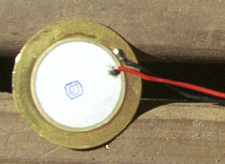
......which can be scrounged from broken telephones, or broken clocks or.. anything which produces monophonic sounds.
c. Some electronic components, which are pretty simple:
a) an op-amp IC like the LM358 or LM741.
b) A potentiometer
c) A schottky diode
d) A donut perfboard.. of course.
2. Glue the piezo transducer to the CD platter using EPOXY GLUE.. very important. The one I did looks like this:

3. Construct the rest of the electronics according to this picture:

This is called signal conditioning... where the output spike is isolated from the rest of electronics by freewheeling the negative spike voltage produced by the piezo transducer using an IN5817 Schottky diode, where it is a diode with a forward voltage of 01-0.2 V only, where a lot of op-amps can only withstand -0.2 inverse voltage at it's non-inverting input, and also the signal is amplified by the gain setting using a single potentiometer. If you don't understand, never mind, just build the circuit. :P
4. The finished product in my project looks like this:

5. Now, you can at least observe the output from a location by placing a voltmeter between the output terminals of the circuit. The output is with regard with the raindrop volume, the higher the volume of the raindrop, the higher the output.
Quantification and calibration techniques will be dependent on the transmission of the data to a PC, where we can utilize the full power of a PC computer to do an acoustic analysis of the signals of the raindrops. We'll cover the data conditioning in further articles, since it is a fully different entity of hardware which needs to be discussed, which is also pretty complex.
Conceptually, the area under the graph depicts the raindrop volume, shown below here is me testing my disdrometer (The graph can be predicted according to the typical output shown in the oscilloscope):

The cost of the network is only around RM4.00... impressively cheap if you're daring enough.
For now, enjoy seeing the output which comes out when rain hits the drum!!
In the following article, we will uncover my most difficult part, which are solid state wind sensors, or anemometers, also built by myself, also with not much documentation in the 'net.
See ya all real soon, InsyaAllah.
Regards,
Vizier87