Showing posts with label Electronics Projects. Show all posts

Sunday, September 22, 2013

An update on Phaserion & Variator: After three years...

Assalamu'alaikum everyone,

It has been a slow year for all of us are busier than ever. However, we're still burning with project ideas. On my side, I have just setup my small working area and I have been using the Phaserion & Variator for three years. (It has been that long? Whoa!).

This time, I'm going to provide some updates on Phaserion, which I think is a very handy equipment I have built all these years. It is an adjustable power supply with a range of 1.5-22V, and I have been using it for just about everything for my electronics projects. 

This is a video of the addition I made for the Phaserion:

Variator with a shiny new display

The feature addition on the Phaserion is pretty important- I added a 7-segment display to indicate the voltage, which is helpful if you have various projects with different supply requirements. The PIC used was the ever-so-simple PIC16F876 (Which I first bought after looking into Nigel's tutorials) and I think it is high time it is permanently embedded into a proper application gizmo for all that I've learnt from Microchip's PICs. We'll have a small tutorial on the 7-segment later, in which the programming was done using MikroC. (I don't think I could have progressed well in my programming if I'm stuck to Assembly language. No hard feelings there Uncle Nigel.). Here's the additional circuit:


A bit of a stumbling block here- How do I detect 22V when PIC is capable only up to around 5V? The answer is simple: A trimpot. Install a trimmer between the output power, and let it swing to it's maximum output. After doing so, slowly tune your pot to give a 5V output. Therefore the output is now 22V Ξ 5V. Swing your voltage down. It will rescale to a lower voltage! 

Some of the pictures may speak a squillion words:


You can see that black-and-white trimmer/trimpot (bought when I was shopping with Beautifulmind seven years ago, you know!) for scaling down 22V maximum swing to a 5V  maximum swing... that'll be for the PIC.


Phaserion adapted for my Starke drill batteries' charging

...and it can be used for my breadboard supply

...Yup. I used my old Chinese multimeter terminals for an in-situ power supply (good for testing nook-in-the-crannies)

Adapted for crocodile clips as well (Just for show dudes)

And since we have so many cables, a good way to organize them would be to use small cardboard cylinders to store 'em cables. Trust me, a good working space is a TIDY one.

So that's all for this article. The circuit addition is pretty simple but we'll cover that later in more detail when the 7-segment tutorial is done.

Keep on Vortexifying everyone! 
Regards,
Vizier87.

Sunday, March 20, 2011

Construct your own DC Power Supply Wall Wart! Variator Reporting.

Alhamdulillah. All Praises to Allah SWT who created and governed everything in this world.

So guys.. we'll be doing something very important for hobbyists here. All electronic circuits require a steady power supply, and you'll get fed up using batteries for testing purposes, which run out of juice for only an hour's worth of running time.. That excludes the electrolytes which leak out after some time.. (NOOOO!!!).....

So.. normally people would opt to: Buy a costly DC wall wart, with fancy controls and an indicator (which is sometimes deceiving) and risk thinning your wallets......

.....or construct their own by buying cheap DC supplies and hacking it to suit their applications. In my experience, after some time the cheap DC supply will be overheated and you'll be left with a fuselage of burnt plastic and a dead transformer.

....or you can opt to take a leaf out of the book of Vortex Electrica and use your own adapters in your house. There are tons of adapters for various applications; Laptop chargers, printer adapters, cellphone chargers (especially old ones), and so on. What's the difference between the ones you buy? Normally adapters for branded stuff have more quality and more protection circuitry. So... This is my collection:


A lot huh? Some of 'em are damaged, and some are okay. Each can be tested easily using an LED and a 100 ohm resistor.

So... the obvious steps for anyone with basics is to cut the wires loose and connect crocodile clippers to them, right?

WRONG! From experience, the weak points are always attributed to the connection between the wire and clip, because the CLIPS SUFFERS THE MOST MECHANICAL STRESS HERE, SO THEY BREAK APART EASILY AFTER SOME TIME. So if you don't want to have to repeatedly re-solder the clips to the wires, the best thing to do is to make separate connections, which can be plugged when in use. In short, see below:


So.. the figure should give an idea. Also, this means that the power from the DC adapter can be plugged into other circuits i.e not only the crocodile clips but also to a breadboard, or any other devices which have the corresponding socket to fit.

Now, another series of ideas comes into play: I want to have.....

a. indicators to know that it is ON, and
b. I want to be able to switch ON/OFF the power at hand, not at the mains where things might get messy, and
c. I want it to be STABLE, not fluctuating power, and
d. I want it to be VARIABLE, not fixed.

So the rest is easy... Add a green LED to indicate ON, a mono-state switch, a filter monolithic capacitor across the terminals, and a variable voltage regulator, like an LM317 or other equivalent components. In short, everything'll look like this:


So as we go along I'll explain the tips and tricks I employed, which may be of use, since we're all about IDEAS at the first place. So here goes:

First Prototype:
VARIATORTM
Wall Wart (I named it for reference... Heh heh..)


So the figure shows some simple stuff:

1. Solder the male socket wiring to the Adapter wiring. In this picture, notice that the GREY insulation is there, standing by to sheath the exposed soldered part of the wiring. This means BEFORE soldering, fit in the insulation first. You can get that type of insulation from various types of wiring which has thicker wires.

2. The exposed part of the wiring is now covered properly by sliding the grey insulation over it. Take note that you have to make sure the inner part of the wiring is also insulated so that no short-circuit takes place. Note that the adapter has a tuning knob there, with fixed values from 3.0,4.5,6.0,7.5 until 21 Volts.

3. Now, add a plastic cover over all the stress points, and glue it accordingly. This makes a nice, difficult-to-break-apart socket. This means if there are any mechanical stress suffered by the socket, the wiring will out of the way, and the plastic cover will take the load. The figure below explains better:


See that the one on the left is one without the casing, so the break points are easily formed at the soldered points, rather than the one on the left, where the load is shifted to the plastic casing, reinforced with epoxy glue.

Next, a conditioning circuit is shown here:


The conditioning circuit is also a separate entity, as declared in the plan before, which fits in a green indicator LED, an ON/OFF switch, a freewheeling diode (to counter backward EMF spikes), a filter capacitor to stabilize supply, and a female USB port.

Now, why did I use a USB socket? Because I have a lot of 'em, and they don't leave room for reverse connection, which could be disastrous. The male USB connector is wired to the crocodile clips, which we'll explain in the following. USB ports have four terminals, so I combined two terminals together to get two crocodile clip terminals.

So now.... The crocodile clips. The main problem with most clips is also due to the mechanical stress it faces. So here's my design:


So the epoxy glue is very important to secure the connections. Also, the plastic casing protects the wiring and shifts the mechanical load of the wiring to itself. The USB socket is a bonus; it's strong and has only a single orientation when you plug it.


The figure above shows the transition according to the design mentioned above.
First, fitting the wires inside the plastic casing. I must warn you, it is pretty tricky to fit in the wires in such a cramped space.
Second, the clips' wiring and gluing is done.
Third, just to show when everything's in place.

So, the conclusion is that while it takes a bit more time to do this, you'll save more time than attending to the wires again and again when they break off due to the wear and tear effect.

So that's it! You have a sturdy Wall Wart for yourself and you don't need to spend much in constructing one. A variant of this (more hardcore DIY-ing) will be provided in future articles, InsyaAllah. For such a simple project, a lot of drilling down is done to provide IDEAS. So.. hopefully some of them will be of use.

All the best to ones out there struggling with their lives... May we live to please Allah more.

Sunday, July 4, 2010

For the Electrical Department's consideration (Lecturers and Students alike)

Assalamualaikum to all Vortex Electrica fans.

One of the problems faced when we, as electronics/electrical students do projects is that very little practical environment pervades within the department. Aside the fact that we all have laboratories, an electronics store to distribute components with the permission of supervisors, some geeks carrying around toolboxes with some perfboard circuits inside, there is still so much to learn regarding electronics.

Kudos to the current Head of Department of Electrical Engineering for making changes to the department, for a lot has changed for the better then, and it is time to move on to further our experience in doing circuits and introduce some tweaks as well.

So how do we start?

For ambitious students, a full fledged tutorial on PIC microcontrollers is the best way to go around it. However we must account for students who are only willing to do simple projects which will make them appreciate the beauty of electronics. And most students are unwilling to spend much money on buying components.

I am not saying my suggestions are the best, but for a lot of subjects, very valuable experiences can be provided to students who do some projects which pertain to the subject itself. Electrical students are divided into four, in my experience:

1. The ones who just want to finish their degree and nothing more
2. The ones interested in doing projects in hardware form (electronics, power, etc.)
3. The ones interested in software/programming
4. The ones who are not interested in anything.

The second and third will be our discussion.

This is the layout of Universiti Malaya's Electrical Engineering curriculum (download the file for a complete listing) which can be used as a medium to do projects:

First year

1. Electronics 1:

-Construct a temperature sensor using an IN4148 diode and some transistors, best marks goes to the ones who manage to linearize the output of Temperature versus Voltage (and the hardware can be passed for further research on low-cost sensors). Should cost only RM10.00 max.

-Drive a relay using different transistors, a report can be done with each team using different transistors, response time, backward EMF study due to relay chatter, how to suppress relay chatter, etc. Costs perhaps RM5.00

-Build a bridge rectifier (Reaaaaaalllllllly frustrating when EE students don't know how to use a damn diode, OKAY!!!) for AC signals. The best marks will be given to the ones with lowest drop-out voltage, and fastest response time, with lowest ripple, and so on. Cost? perhaps RM3.....

-Build a H-Bridge to control motors using transistors. Best marks to the ones who manages lowest drop-out voltage, highest input/output current ratio, efficiency, etc. Each team will use different transistors, zero marks to duplicate circuits. Cost?.. I think RM15.

2. C++ Programming:

-Change it to C programming, and let 1st year students blink an LED or two at the generic PIC main boards. Using a PIC12F and some perfboard, the circuit can be completed in one day, costs at most RM 10. More advanced programming? Drive a motor speed using PWM. More? Interrupt. More? At your discretion.

3. Digital Systems

-Build logic gates using diodes/transistors. Each team will be assigned to different types of diodes, and different gates as well. Cost? Less than RM5, assured.

-Learn to use Flip-flop ICs/Logic Gate ICs and do some applications. Cost? Less than RM15.

....And so on.

2nd year

4. Electronics 2:

-Amplify signals from the heart using any type of sensor. Cost: RM 20. Best marks go to the ones who manage the best accuracy compared to a standard ECG.

-Make different types of filters/instrumentational amplifier using op-amps (SAY NO TO THE LOUSY 741 ICs!!!) Cost: RM 5

-Process signals from various sources using a software in a PC. Like quantifying heartbeat signals, bird calls, light intensities, temperature, and so on.

-Build an oscillator using op-amps.

.....And other millions of op-amp projects.

5. Instrumentation

-Start using PICs to drive motors, detect readings using ADC, display signals, use temperature signals, strain gauges, range sensors like IR diodes, RF modules (315 or 418 MHz ones), drive relays to operate a 30V motor, for instance... and so on. This project has most options actually. Cost: From RM 20-100.

6. Electric Machines

-Build motors... Now this is very fun. Different motors for different teams, so students can build stepper motors, DC brush motors, brushless motors, relay switches, alarms, etc, anything which requires electromagnetism and mechanical motion. We managed to introduce this culture during our 2nd year. Voila!!

3rd Year

7. Electromagnetic Theory

-Build RF modules. Longer ranging, the better. Give some restrictions: Doesn't introduce interference to the existing signals (otherwise it'll jam things up), low power, and so on.

-Build inductive current sensors, like the ones used in Power Electronics Labs.

8. Microprocessors

-NOW.... proceed to using higher quality PICs and give 'em any kind of project which involves sensors, robots and whatnot. Too many projects are on the 'net. Build a frickin' Asimo if they want.

9. Energy Conversion & Power Transmission

-Again, we manage to be the pioneers of projects involving generators. We can settle down with the DC/AC generators, or also explore Solar Cells, Wind Power Turbines, Thermal Energy, and so on.
Example: Make a portable battery charger using a small water tank which is heated up to propel a turbine to charge a cellphone. Campers can use it when they're going in jungles, so when they make bonfires, they also can charge their cellphones. Also, with solar cells too.


10. Feedback Control Systems:

-Aha.. there is so much we can do around here. I suggest: Build a coffee-maker using stepper motors, which need to be modeled using Laplace/Fourier/Z Transforms. This utilizes transient responses of the motors as well. Usage of PICs required.
Also, we can build a simple pick-and-place robots using PICs and servo motors too.

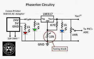
11. Power Electronics:

Build your own buck, boost, buck-boost, Cuk, and so on Regulators. Is it so difficult? We'll never know if we don't try. The problem is many EE students don't even understand the meaning of Power Electronics.

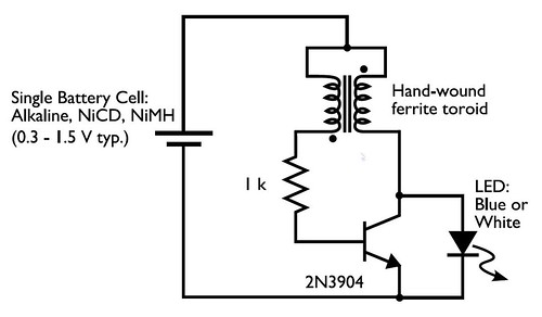
There is one very interesting circuit:


It demonstrates the usability of a nearly dead cell to power up an LED! Therefore it 'boosts' the voltage, demonstrating the significance of power electronics and boost circuits. This project can be assigned EASILY!!! So why do we hesitate in giving students such simple projects?

In conclusion, look at how much projects can be done with just Googling around. To the ones who think it ain't important, I'll just ask one simple question: What do you remember during lectures? Even for a geek like me, I remember nothing except jokes from lecturers!! BUT I remember nearly every detail of projects done by our Team VORTEX ELECTRICA, and it is the memory which made me value the experience in the University. I'm sure all the other members felt the same way.

I hope future Malaysian students who take up EE in any university will ask their lecturers to give projects like these. They're fun and most importantly, life is a lot about memories, and this is an experience which will be hard to be obtained in the times you are already working.

And oh, if you're going to bitch about cost of the projects, remember that you have spent more on food in a single day than most of these projects! So to the lecturers out there (if you're reading this) just give the projects to them and you'll be surprised how capable Malaysian students are actually! This SHOULD be the main part of the continuous assessment for the students. Honestly, I'd put 30% on projects, and 10% on tests/assignments. The rest is exams, and it's fine by me. To me, all that mattered during my tenure (academically speaking) in UM are three things: Kind lecturers who demonstrates "formidability", the three projects in hardware form assigned by lecturers themselves, and finally our final year project. The rest will be very scantily remembered, sorry to say, even the labs and equipments don't mean much to me except the times I actually needed it.


Vizier87 is signing out.

Wednesday, February 24, 2010

Solid-State Weather Systems Electronics: Part 1

This would be one of the didactic posts I'll be putting here... since we're gonna talk about electronics... but wait.. I can't be serious for a minute! So here we are breathin' and talkin' electronics like we're talking 'bout football (except I DON'T talk about football).

Let's start with the first three weather parameters which doesn't need secrecy: Ambient temperature, humidity and barometric pressure. To newbies in electronics, keep this in mind: DOWNLOAD DATASHEETS OF ANY COMPONENT YOU'RE USING, EVEN IF IT IS A DIODE!!!

Ah, I'd like to note: I won't elaborate too much on the electronic connections and circuitry because Google contains billions of 'em, including crappy ones. The best testimony that can be obtained by an electronics hobbyist is a hands-on experience, so please don't expect things to run smoothly after you've connected every terminals with that thinking that you followed a RANDOM circuit you took from Google is said to be FUNCTIONAL by a RANDOM blogger, so your circuit must work. Anyways, you'll still make that mistake everyone commits: the thought that "the circuit is provided, problem solved." so be my guest, make the mistakes, and you'll learn it the hard way.

Firstly, an LM35DZ is a simple thermal sensor which I used for ambient temperature detection, manufactured and used by the billion, so there's nothing much to it. In stores they usually cost RM5.00 (about 1.50 USD) and Farnell (an international electronics components distributor) offers much better prices.

Figure: LM35 Centigrade Sensor


To anyone using it, or who wants to use it, remember that there is a very important rule: connections! See the figure below:

Note that it is a BOTTOM VIEW!!!! I made this simple mistake and wasted a lot of time so don't mess your sensors!!
So after this, give it a supply of 5V from a voltage regulator LM7805. This'll cost another RM1.50.

Second, humidity sensors... I used HCH1000 capacitive humidity sensor, which is the hygrometer for my weather station and the cheapest by far, around RM26. See below:

Figure: Honeywell's HCH1000 capacitive humidity sensor

This sensor needs to be conditioned according to a circuit provided by the datasheet for HS1101-HS1100 here and the circuit is here:
Figure: Circuit for HCH1000 capacitive humidity sensor conditioning

You'll need to adjust the ratio between R4 and R2 and I added a 10uF non-polar capacitor in series to the HCH1000 to make the response readable by my Digital Multimeter (DMM) in frequency read mode (Buy a good DMM, not the cheap Korean or Chinese ones). Note that it took me a lot of time just to find the right links to introduce these fine adjustments so go figure if yours didn't work.

To test the sensor, put a damp cloth or tissue near the sensor, and the frequency of the timer output will reduce. This frequency'll be used to be translated in PIC microcontrollers (See Deathclaw's intro into microcontrollers in this blog if you don't know anything about microcontrollers here) or you can visit this page: Nigel's PIC page.

Third part: Barometric pressure sensors... I chose the cheapest one, MPX4115A available with a price of RM39.00 by Farnell. This sensor is very simple but the documentation regarding it sucks in the 'net. Don't look at the the datasheets if you're figuring out the pinouts, they'll confuse you with three 'styles' of terminals... see this figure which is painfully extricated from a book by Ibrahim Dogan:

Figure: MPX4115A pin descriptions

This sensor detects changes in barometric pressure, translated in outputs of voltage, so it's simple because its output is from 0-4.8V for a supply of 4.75-5.2v (plug-and-play component, no amplification needed).

For what's worth, I've presented 6 months of research (finding each sensor took a lot of time!!) and labor where the simplicity of these things are evident. Mistakes have been made and rectified, so I hope this'll pave an easier route for weather systems' researchers who wanted to build a solid-state weather system on their own.

Alhamdulillah, all this experience is very humbling to me since the more work is poured, the more I realized how much I didn't know about the complexity and beauty of electronics in the human body (no one has been able to explain why images in the brain, in the region of nanovolts doesn't get mutilated in the presence of even the strongest magnetic fields like in MRI- Magnetic Resonance Imaging machines, where electronic cameras get fuzzed easily with Electronic Jamming devices.) Masya-Allah. This is also the case in weather systems, even with the advancement in technology nowadays, weather prediction are always done with a certain amount of certainty, but it is never certain.

I'll cover the more powerfully complex parameters for the electronics in the next part, which is rain precipitation, wind speed and wind direction. Stay tuned with Vortex Electrica!!!!


Allah has made Vortexes ubiquitous in nature!

Regards,
Vizier87
Related Posts Plugin for WordPress, Blogger...