Showing posts with label DIY. Show all posts

Sunday, October 21, 2012

A comparison between quality of ADCs: Texas Instruments' ADS1100 16-bit and Microchip's 10-bit ADC

بسم الله الحمدلله والصلوة والسلام على رسول الله

Salam'alaikum guys.
I have collected an incredible amount of documentation for this blog's material to make more articles, but I'll release it slowly, insyaAllah. 

So, as per the title, you may wonder if this is really hobbyist stuff. As a Microchip user, I had a lot of problem using only 10 bits for my ADC, when the last (10th) bit is usually not very useful anyway since it fluctuates a lot due to electrical noise. Now, I'm not going into how ADCs work, since this article will be for faithful PIC users. And just for the record, I'm a PIC fan, and I'm not telling people to criticize Microchip for their features. This is just a not-your-average-academic report on performance comparison.

I obtained a lot of samples from Texas Instruments, therefore I feel that I could express my gratitude by putting this report out. Thanks to all the staff who handled the shipping of TI's products, from Thief River Falls. The ADC of our concern will be primarily by TI, the ADS1100. This chip has 15-bit code output for single ended inputs, communication using I2C, self calibrating, low power consumption, and awesome. The other one will be from PIC184620F's hardware ADC, which is similar for most PIC hardware ADCs.

The one I received is mounted (or wire-bonded) like this:
Figure 1: ADS1100 mounted for 2.54mm receptacles
The chip is an SOT-223 package, a bit small but possible to be mounted on a perfboard. A bit of soldering expertise required but not an issue here. It'll be easier to connect to the main board after you've finished. It's quite easy to solder on a PCB too.

This is perhaps just a simple ADS1100 tutorial:
1. Setup the circuit as shown below: (Remember to add a pull-up resistor for SDA and SCL.)

Figure 2: Single-ended input for ADS1100 (From ADS1100 Datasheet)


2. Connect SCL and SDA to your microcontroller (I'm using Microchip's PIC... they're still cool). You can choose either a hardware or software I2C, but sometimes because of design limitations, a software I2C is much more practical. You need a quick intro into I2C and try to write your own I2C software , but nowadays you can cut to the chase and use libraries which are supported by microcontroller compilers. MikroC is one of those.

The code will be something like this (using MikroC):

///////////////////////////////////////////
  Soft_I2C_Init();               //  Software SPI initializing.
  Soft_I2C_Start();            //  a. Initiate a start 
  Soft_I2C_Write(0x90);   //  b. Sends address to ADS1100 at 0x90. Refer datasheet at address section. 
  Soft_I2C_Write(0x8c);   //  c. Default value (0x8c) to be written to the chip. Refer datasheet for more.
  Soft_I2C_Stop();            //  d: Stop signal
///////////////////////////////////////////

After receiving these commands, the ADS1100 performs conversion and stores them inside its register, with a value from D14 to D00. One bit is lost due to this configuration (can't be helped, there's an extra measure you can take to recover the lost bit as pointed out in the datasheet but 15 bits is enough for me)

3. Now you can retrieve the 15-bit code:

//////////////////////////////////////////////////////     
     Soft_I2C_Start();                    // Start software I2C
     Soft_I2C_Write(0x91);           // Write to threaten the ADC to send the data it's hiding. Gimme gimme!!
     highbyte=Soft_I2C_Read(1);  // Read the seven most significant bits (D14-D08), send an ACK    
     lowbyte=Soft_I2C_Read(0);   // Read the remaining D07-D00 data bits, and send a NACK.    
     Soft_I2C_Stop();                    // Stop or else you'll be desoldered. (just joking guys).
//////////////////////////////////////////////////////

Loop this code for a continuous reading, and send this data to the PIC's GPIO ports with LEDs to see the outputs, let's say portd=highbyte and portc=lowbyte. MikroC's software I2C is rated at 20kHz, which is sufficient for our demonstration. Later, we can manipulate these data for our use.

***********************************  End of tutorial  **********************************

Comparing an ADC chip with an ADC hardware inside a microcontroller might be like comparing apples and oranges since the intended usage of ADCs varies from user to user, and people'll be like, "C'mon! One is 16-bit and the other 10-bit! That's unfair!" But for me, what is interesting is the fluctuation of the least significant bit of both of these ADCs, and we'll see that in a moment through this video: 

Video: ADS1100 demonstration 

So in conclusion, we can see that the ADS1100 gives a much stabler output at a very precarious resolution (i.e. 5V/32767=0.00015V) compared to Microchip's 10-bit output (5V/1023=0.0045V) and we see a lot of noise going on there!

So that's it! If you want the code, please download it here, which shows the output of both the ADS1100 and the hardware ADC output via an LCD display. It's a bit messy and I'm not an expert programmer, but hope it helps!

All the best to everyone.
Vizier87.

Friday, October 1, 2010

Jumper Cables from Junk

Ach-tung to all VE readers!!

I think I owe an apology for not regulating this site, since we're all out of the juice needed to write articles here. I'll be giving some simple, very simple stuff which no-one has done yet, at least in my circle.

Beautifulmind and Deathclaw are pretty busy engineers at the moment, and I'm kinda busy too.. but in a different way since I'm not working or continuing my studies yet, and yes, I'm going for the latter after this. So... Enough of my lugubriousness here... we'll get to the topic now.

One aspect of being an electronics hobbyist is that we'll need to channel voltage/current supply to our circuits or motors or even a single LED to a Wall Wart or a DC Supply or a battery. Rather than using wires to touch the terminals using your hands, or doing that messy temporary soldering to connect the terminals, people like to use jumper cables.

Heard of this one before?
"The strength of a chain lies in the weakest link"

This is also the golden rule with jumper connectors. No matter how beautiful or strong the grip is, you'll always end up with broken jumper connectors with the usual crocodile clips. This is because the wires are not adhered to the clips properly. You'll notice it takes more than soldering the contacts to have good quality jumper cables.

There is absolutely nothing going on here except that you'll notice: You don't need to buy the jumper cables, you don't need to be a geek to build one, and you certainly don't need to fish out three or four bucks for each jumper connectors which USUALLY don't last and will need to be repaired after some time due to wires breaking off after some time, which is due to the mechanical stress.

So.... Naturally mistakes were made, and better solutions were discovered...According to five years of experience of building my own jumper cables, I'll name a few ingredients needed for this recipe (assemble your junk collection and you'll get more options, these are only the ones I made, you might be able to make better ones):

1. Name Tag clips, which are made out of steel. They're very strong, and the grip is MUCH stronger than the generic crocodile clips., they have holes which aid in knotting or fitting in other strengthening elements. Here's my collection after extracting 'em from various name tags:


I used pliers to pull out the aluminum rivets which hold the plastic and the steel clip together. Notice that the rightmost one is an anomaly, that one is cut from plastic name tags which has the metal clip part on it. It serves a lot of purpose too.

2. Wire. (Duh!!) I got mine from radio wiring, they're very sturdy and thick, which means the tolerance is much higher if you're considering heating problems in your connections which require a large current.

To be taken into consideration: We're building jumper cables, which are prone to a lot of mechanical stress (wear and tear) so it'll be nice if you have the type of wires with a groovy and fancy-looking insulation at the end of the wire, which may be salvaged from basically all type of appliances. Something like this:


The fancy-looking "grooves" on the wire will be very helpful in making the glue bond between the wire and the clip very strong and durable.

3. Epoxy Glue: Please view this link.

The steps are pretty obvious, so I wouldn't want you to waste time reading details which don't matter, but I'll put up a single picture to show how I did it:


The picture above shows the soldering process (solder sticks pretty properly, don't worry). And a combination of the full-steel clip and the half-plastic half-steel clip is VERY useful for some applications.

The picture below are the variations of my construction for other cables:


Description:
a: The red highlighted area is the part which will be soldered, note that the wires are wounded around the upper part before putting it to contact with the metal surface of the clip. This aids additional strength of the connection after gluing.

b: The next sequence shows the contacts are soldered generously, and the "groovy" part of the fire is fitted into the hole of the clip, which again adds a significant durability to the "weakest link" (yes, in my experience, this is the frustrating part) after the applied glue to the crevices dries and hardens up.

c: This picture shows another technique used; I looped the wire around the hole (which is why name tag clips are just the thing for this purpose) and I glued the loose part.

After all of this is done, my collection is displayed as follows:


When everything's all said and done...... BOW DOWN!!! You have your own collection of the strongest type of jumper connectors for your electronics projects. Connect it to motors, LEDs (with resistors, I must remind you people), breadboards (stick a male connector into it and clip to the revealed part), and so on.

I know this article is pretty light and simple, but I find that these cables provide to be more than a chain to the missing link (intended there) which is called: convenience.

InsyaAllah, may God be pleased with us for living our lives trying to spend less (by improvising and recycling more) and use the money for better purposes.

Vizier87

Tuesday, June 1, 2010

Solid-State Weather Systems Electronics: Part 2>> Acoustic Disdrometer Rain Sensors

Hi guys.. I've just finished my thesis project documentation, now I'm taking a break in my home. This is the next part from my final year project in this blog, a continuation from the article: Solid-State Weather Systems Electronics: Part 1

Where the first article has the least difficulty regarding detection of three weather parameters: Ambient temperature, humidity and Barometric Pressure.

---------------This article has a moderate difficulty level in construction.--------------

Remember that the documentation regarding this article is pretty scarce, since most of the sensors out there are tested using million-dollar equipments, therefore they are patented technologies. I'm just doing this project from a hobbyist perspective... so if you manage to build an industrially-challenging one, good for you! References in the internet regarding rain sensors can be done by yourselves, but I'm gonna put forward ORIGINAL research and WORK done here... and the RESULTS are all original as well... So hopefully we're not part of useless Google searches regarding DIY Rain Sensors.

So.. We have come to the next parameter, which is pretty complex to process, but the hardware required is pretty simple. Yep, we're gonna do a rain check here.. So what is the importance of reading rain? Not important at all, if you are a common guy, but it may have a lot of significance to a farmer who wants to monitor his crops for farming precision. Remember that agriculture is a very-very important field in Malaysia, where a paddy field in Kedah,Malaysia will certainly benefit from precision in rain-reading, Insya-Allah.

First things first- how do you sense rain? How do you know if it's a torrent or a drizzle out there when you're sitting in your home snoozing or drinking milk tea? You know the answer, but it is difficult to answer it using technical terms. So I'll do my best to describe what I'm doing here to a layman.

There are several techniques used, apart from the standard but disgustingly bulky rain gauges (if you don't know about rain gauges you can do a quick wiki here.)

As for rain detection, the following electronics solid-state designs are briefed after processing the 'net's worth of info. NOTE: There are surprisingly very little amount of documented projects regarding DIY rain sensing.. so the combination of info is siphoned into a useful collection of info, hopefully... :)

i) Drop count: Water drips from an orifice that produces drops of known size which are
usually counted optically (which means the usage of optical sensors like Infrared, or light intensity fluctuation detection>> How to imagine the function: It's like seeing a mutilated image of a person at the back of an aquarium, since the water produces aberrations in the light... oh well that clears THAT.). This design is good for light rain, responds quickly to the changes, but requires a reservoir be maintained at a certain level. Ain't good if you're measuring light rain.

ii) Optical rain gauge: This technique uses scintillation effects to detect/calculate rainfall. This
is an electronic solution which is very pricy, since optics requires a lot of complex analysis. This
design is good for rates, but it is easily deceived by fog and mist. Used by Malaysian weather researchers or whatnot MOSTI... The concept is similar to the one used in the drop count. Xenso (A company making sensors) sells them at $99 (RM 300) to 'em weather guys in Malaysia.

iii) Self-siphoning capacitance gauge: This contraption uses a collection tube with a level
gauge, which is self emptying. This is a good method for measuring rainfall accumulation, which not good for light rains. Hard to DIY. No explanation needed since I don't understand it anyway.

iv) Doppler detection: This method uses reflected microwaves to determine intensity. This is an electronic solution which requires a high level of technology, meaning high cost issues. Even I could find much documentation regarding this thingy. Again, I still don't understand it too.

v) Ultrasonic sensors: This method is also an electronic solution, and also very pricy. It
measures rain by detecting the interference signals generated by the raindrops in an array of
ultrasonic network systems. EXTREMELY hard to DIY. And again, I don't understand the details much too. :(

vi) Disdrometers: AHA!! Bingo!! This concept uses impact of rain, where rainfall is measured by detecting the raindrop impacts via a piezoelectric sensor, which produces a voltage proportional to the volume of the raindrop. Used in the $3850 WXT510 Weather Transmitter (You're a fool to not sense a hint of sarcasm in this sentence)

Heh heh.. But this last option above proves to be the easiest to reverse-engineer and DIY, since Vortex Electrica is ALL about saving money and still being able to do kick-ass projects!! Credit needs to be given to Rolf Hut in his Instructables project.
The details regarding the electronics and techniques of detection are original, from Vortex Electrica though.

So.... what are DISDROMETERS? It is a meter which detects impact, simply put. A raindrop has impact, therefore a disdrometer reads it. The simplest analogy I can give is: Imagine a microphone being tapped by your finger. What does it produce at the speakers' end? TAP! TAP! TAP! Similarly, when you're sitting in your room, you know whether it is raining heavily or not. Now... to make it analyzable and quantifiable... we're gonna start on the construction:

STEPS IN BUILDING A DISDROMETER:

1: You'll need:

a. A plastic CD/DVD platter (or something flat, take your pick)
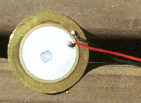
b. A piezoelectric transducer, like shown here:


......which can be scrounged from broken telephones, or broken clocks or.. anything which produces monophonic sounds.

c. Some electronic components, which are pretty simple:
a) an op-amp IC like the LM358 or LM741.
b) A potentiometer
c) A schottky diode
d) A donut perfboard.. of course.

2. Glue the piezo transducer to the CD platter using EPOXY GLUE.. very important. The one I did looks like this:

3. Construct the rest of the electronics according to this picture:


This is called signal conditioning... where the output spike is isolated from the rest of electronics by freewheeling the negative spike voltage produced by the piezo transducer using an IN5817 Schottky diode, where it is a diode with a forward voltage of 01-0.2 V only, where a lot of op-amps can only withstand -0.2 inverse voltage at it's non-inverting input, and also the signal is amplified by the gain setting using a single potentiometer. If you don't understand, never mind, just build the circuit. :P


4. The finished product in my project looks like this:


5. Now, you can at least observe the output from a location by placing a voltmeter between the output terminals of the circuit. The output is with regard with the raindrop volume, the higher the volume of the raindrop, the higher the output.

Quantification and calibration techniques will be dependent on the transmission of the data to a PC, where we can utilize the full power of a PC computer to do an acoustic analysis of the signals of the raindrops. We'll cover the data conditioning in further articles, since it is a fully different entity of hardware which needs to be discussed, which is also pretty complex.

Conceptually, the area under the graph depicts the raindrop volume, shown below here is me testing my disdrometer (The graph can be predicted according to the typical output shown in the oscilloscope):

The cost of the network is only around RM4.00... impressively cheap if you're daring enough.
For now, enjoy seeing the output which comes out when rain hits the drum!!
In the following article, we will uncover my most difficult part, which are solid state wind sensors, or anemometers, also built by myself, also with not much documentation in the 'net.

See ya all real soon, InsyaAllah.


Regards,
Vizier87

Sunday, April 4, 2010

Construct your own Electric Generator!

Establishing Server Connection to VE headquarters......
.
.
.
.
.
Connection secured.

Hi guys, (or gals?) this is an overdue article on our third year project on Energy Conversion and Power Transmission, by our lecturer, who was our also our Electrical Machines lecturer. I figured out that now I have some time to impart the depths of the Vortex Electrica secrets which should be shared. Since our DIY motor project has gained a reputation with our lecturer, he was inspired to tell us to build a generator. The VE bloodline is again revived!! So here we are.

The most satisfying aspect of building a generator is you can see a form of energy that can't be harnessed properly, and it transfers itself into something that can be properly used (like charging a battery from wind flow, an so on). See the video:


Output Demonstration

Why did I post the video first? This is just for you guys who are skeptical at our product. So we'll just impart it all for you to see. This generator generates 30V at around 3500 rpm (revolutions per minute) with no-load (that means the terminals are directly fed to a voltmeter/multimeter. So how are you gonna build it? The concept is too simple since you guys can also see the link regarding our DIY motor: Here

Basic concepts and physics regarding generators can be read from the wiki here:
Concepts on generators
.... and please read 'em properly if you're a complete newbie.

Anyway, here's a simple diagram on our construction (this diagram is property of Vortex Electrica, references must be with citations) :


From the diagram, (study it carefully!!) The construction is pretty simple, and saves a lot of time regarding analysis. The reason we used this design (which is not the best, since industrial generators use more complicated but efficient windings) is to save you from the trouble of winding and re-winding it due to mistakes. Trust me, the biggest problem in construction of this thing comes from winding the coils, which may be up to thousands of repeated windings. You'll not want to unwind 1000 windings after discovering that the generator has problems regarding orientation or discontinuity of the coils. The details regarding winding configuration will be covered in the following sections.

Here comes the important part: Construction.
What are the ingredients we used? Here you are:

1. Broken hard-drives:


We'll need the permanent magnets from these hard-drives, which are NEODYMIUM magnets. These magnets are the strongest magnets ever produced in the industry. A good documentation regarding hard-drive magnets can be seen in this link: Neodymium magnets
A very good tip: You can get them virtually for free or for very cheap prices if you haggle the prices properly in some shops selling computer hardware, where they usually keep scrap hard-drives for scrap metal, but they'd gladly sell them to you for RM2-RM5 apiece.

2. A non-magnetic metal shaft (can be found in CD-drives)

3. Copper coils is pretty easy to obtain cheaply, from broken transformers and so on, but we bought CRT field coils (from old TVs) for RM10 from a shop selling CRTs. You can get yours for free if you have broken TVs in your attic/store. Haha!!

Here's some pictures:

CRT field coils : RM10, undismantled


Extracted copper coils


It takes great patience to extricate the coils, which are bonded together with resin, but you'll manage, InsyaAllah.

Now, the basic ingredients are covered. Now, we'll proceed to construction, where the other materials will be described as we go along.
Construction:
A) First Sequence:


Framework for the generator

Description:
1. Neodymium magnets on brackets

2. Separated magnets, that's how those magnets look like

3. Halved for polarity isolation (see the documentation regarding Neodymium magnets on the link above. In our case, since cutting it in half using non-magnetic blades is not an option, we used a steel hacksaw to make a dent at two positions for weak stress points, then carefully snap 'em in half using your bare hands, they ARE that brittle, so make the dents sparingly)

4. Armature built using the non-magnetic shaft (usually you can get 'em from toys/CD/DVD drives) we held together the magnets with the tubular structure using epoxy glue (A VERY IMPORTANT COMPONENT!!!). The white tubular structures are actually ballpoint pen casings. Very strong and reliable structural material!

5. Materials for the generator frame (we omitted the metal screws for they produce a very large reluctance in the armature movement.)

6. The basic framework completed, note the neodymium magnets' orientation, please use this configuration.

B. Windings:
The pictures here are simpler, just to show the coiling progress:


Winding orientation: Two planes of separate winding (Singular winding shown in the figure is for simplification, you'll need to wind as much as you can for both planes SEPARATELY, combined after completing the space provided by the generator framework.)


Description:

1. Coiling like normal: Remember, the coils are separate between the two planes we used to maximize the space usage. Combination between the two planes are done after the winding is completed.

REMEMBER: We coiled one plane, then the other after completing each layer alternatively, this way the coils are uniform (imagine this like doin' hamburgers, you don't make two big layers, you put thin layers of goodies but lots of it alternatively, like bread,meat, salad, dressing, then fried egg, then dressing back, salad, meat and bread in the bottom)

2. Hmmm... are we done? The CRT coils are still abundant.

3. We added an extra nozzle (the white plastic thingy) to increase the winding space and to avoid the coils from colliding with shaft.

4. Covered some of the parts with tape to hold the windings in place, they tend to loosen after a 2 cm layer worth of coils.

5. Looks like an egg ain't it? That's what we called it, "The Golden Egg"... the thing can roll like one too. Hahaha!!

6. VERY IMPORTANT: Make sure you test the output from the coils after completing a number of thin layers. Just directly connect an LED to the terminals, if there is no output you'll just have to unwind a small number of windings rather than unwinding the whole damn thing.


C: Finalization

Finalization on Structure and Testing

Description:
1. Covered with electrical tape to rigidify the fuselage

2. A presentable platform, using plastic frames from the CRT and some other scraps, held together using screws and epoxy glue.

3. Testing the output by connecting the generator shaft to a shaft of a DC motor.

4. The outputs are indicated using LCD display (Special division of programming of the PIC by Mr. Fakhruddin (Deathclaw)

Alhamdulillah, the result is extremely satisfying as we've managed to produce the prototype properly and met the objectives with the best output/efficiency (30V DC output for us, other teams got 3V at most, smallest weight/volume and weight/output power ratio also).

Both the outputs are rectified using our own Bridge Rectifiers, each windings got one. Both the rectifiers are connected in series to produce a combined DC output:

Vortex Rectifier Circuit Diagram

This is the final picture of the presented prototype:


All the personnels are involved in the completion of this project:
1. Abdul Halim Poh (Vizier87), Electromechanical Systems
2. Shahrilhafiz (beautifulmind), Power Electronics
3. Fakhruddin (Deathclaw), Programming
4. Nazmi Zulkifli, Team Manager
5. Mr Lew Han Kit, Misc. Assisting Personnel.

There were many mistakes made and we rectified the problems one-by-one, not to mention the pain we experienced due to the wires which tore after the sharp edges of the revolving magnets cut it for being too close, and at one time the magnets flew apart because of the unbelievable velocity of spin, and also two scrapped major designs, each taking a LOT of bloodshed, and for the ones who wish to add an external revolving field similar to this:

.... With the assumption that it will make the output larger with denser magnetic flux, IT'LL NOT WORK, and the output will be even less. This is true for our case and another team's generator. Anyone who can submit the reason, please do so, and your name will be embedded in this article for giving the explanation.

Thanks to everyone involved. May Allah bless us all with the understanding of His creations and ultimately seek refuge under his mercy.

Regards,
Vizier87

Wednesday, February 24, 2010

Solid-State Weather Systems Electronics: Part 1

This would be one of the didactic posts I'll be putting here... since we're gonna talk about electronics... but wait.. I can't be serious for a minute! So here we are breathin' and talkin' electronics like we're talking 'bout football (except I DON'T talk about football).

Let's start with the first three weather parameters which doesn't need secrecy: Ambient temperature, humidity and barometric pressure. To newbies in electronics, keep this in mind: DOWNLOAD DATASHEETS OF ANY COMPONENT YOU'RE USING, EVEN IF IT IS A DIODE!!!

Ah, I'd like to note: I won't elaborate too much on the electronic connections and circuitry because Google contains billions of 'em, including crappy ones. The best testimony that can be obtained by an electronics hobbyist is a hands-on experience, so please don't expect things to run smoothly after you've connected every terminals with that thinking that you followed a RANDOM circuit you took from Google is said to be FUNCTIONAL by a RANDOM blogger, so your circuit must work. Anyways, you'll still make that mistake everyone commits: the thought that "the circuit is provided, problem solved." so be my guest, make the mistakes, and you'll learn it the hard way.

Firstly, an LM35DZ is a simple thermal sensor which I used for ambient temperature detection, manufactured and used by the billion, so there's nothing much to it. In stores they usually cost RM5.00 (about 1.50 USD) and Farnell (an international electronics components distributor) offers much better prices.

Figure: LM35 Centigrade Sensor


To anyone using it, or who wants to use it, remember that there is a very important rule: connections! See the figure below:

Note that it is a BOTTOM VIEW!!!! I made this simple mistake and wasted a lot of time so don't mess your sensors!!
So after this, give it a supply of 5V from a voltage regulator LM7805. This'll cost another RM1.50.

Second, humidity sensors... I used HCH1000 capacitive humidity sensor, which is the hygrometer for my weather station and the cheapest by far, around RM26. See below:

Figure: Honeywell's HCH1000 capacitive humidity sensor

This sensor needs to be conditioned according to a circuit provided by the datasheet for HS1101-HS1100 here and the circuit is here:
Figure: Circuit for HCH1000 capacitive humidity sensor conditioning

You'll need to adjust the ratio between R4 and R2 and I added a 10uF non-polar capacitor in series to the HCH1000 to make the response readable by my Digital Multimeter (DMM) in frequency read mode (Buy a good DMM, not the cheap Korean or Chinese ones). Note that it took me a lot of time just to find the right links to introduce these fine adjustments so go figure if yours didn't work.

To test the sensor, put a damp cloth or tissue near the sensor, and the frequency of the timer output will reduce. This frequency'll be used to be translated in PIC microcontrollers (See Deathclaw's intro into microcontrollers in this blog if you don't know anything about microcontrollers here) or you can visit this page: Nigel's PIC page.

Third part: Barometric pressure sensors... I chose the cheapest one, MPX4115A available with a price of RM39.00 by Farnell. This sensor is very simple but the documentation regarding it sucks in the 'net. Don't look at the the datasheets if you're figuring out the pinouts, they'll confuse you with three 'styles' of terminals... see this figure which is painfully extricated from a book by Ibrahim Dogan:

Figure: MPX4115A pin descriptions

This sensor detects changes in barometric pressure, translated in outputs of voltage, so it's simple because its output is from 0-4.8V for a supply of 4.75-5.2v (plug-and-play component, no amplification needed).

For what's worth, I've presented 6 months of research (finding each sensor took a lot of time!!) and labor where the simplicity of these things are evident. Mistakes have been made and rectified, so I hope this'll pave an easier route for weather systems' researchers who wanted to build a solid-state weather system on their own.

Alhamdulillah, all this experience is very humbling to me since the more work is poured, the more I realized how much I didn't know about the complexity and beauty of electronics in the human body (no one has been able to explain why images in the brain, in the region of nanovolts doesn't get mutilated in the presence of even the strongest magnetic fields like in MRI- Magnetic Resonance Imaging machines, where electronic cameras get fuzzed easily with Electronic Jamming devices.) Masya-Allah. This is also the case in weather systems, even with the advancement in technology nowadays, weather prediction are always done with a certain amount of certainty, but it is never certain.

I'll cover the more powerfully complex parameters for the electronics in the next part, which is rain precipitation, wind speed and wind direction. Stay tuned with Vortex Electrica!!!!


Allah has made Vortexes ubiquitous in nature!

Regards,
Vizier87
Related Posts Plugin for WordPress, Blogger...